
Pump System Design Guide
A practical pump system design guide: define duty flow and head, draw the system curve, size the suction piping, protect the NPSH margin against cavitation, and match the pump technology to the liquid.
Pump system design starts with the duty — the flow rate and the total head the pump must deliver. Total head adds static lift (height and pressure difference) to piping friction losses; together they form the system curve. The pump is then chosen so its head-flow curve crosses that system curve at the required duty point, with suction piping sized to keep available NPSH safely above the pump's requirement.
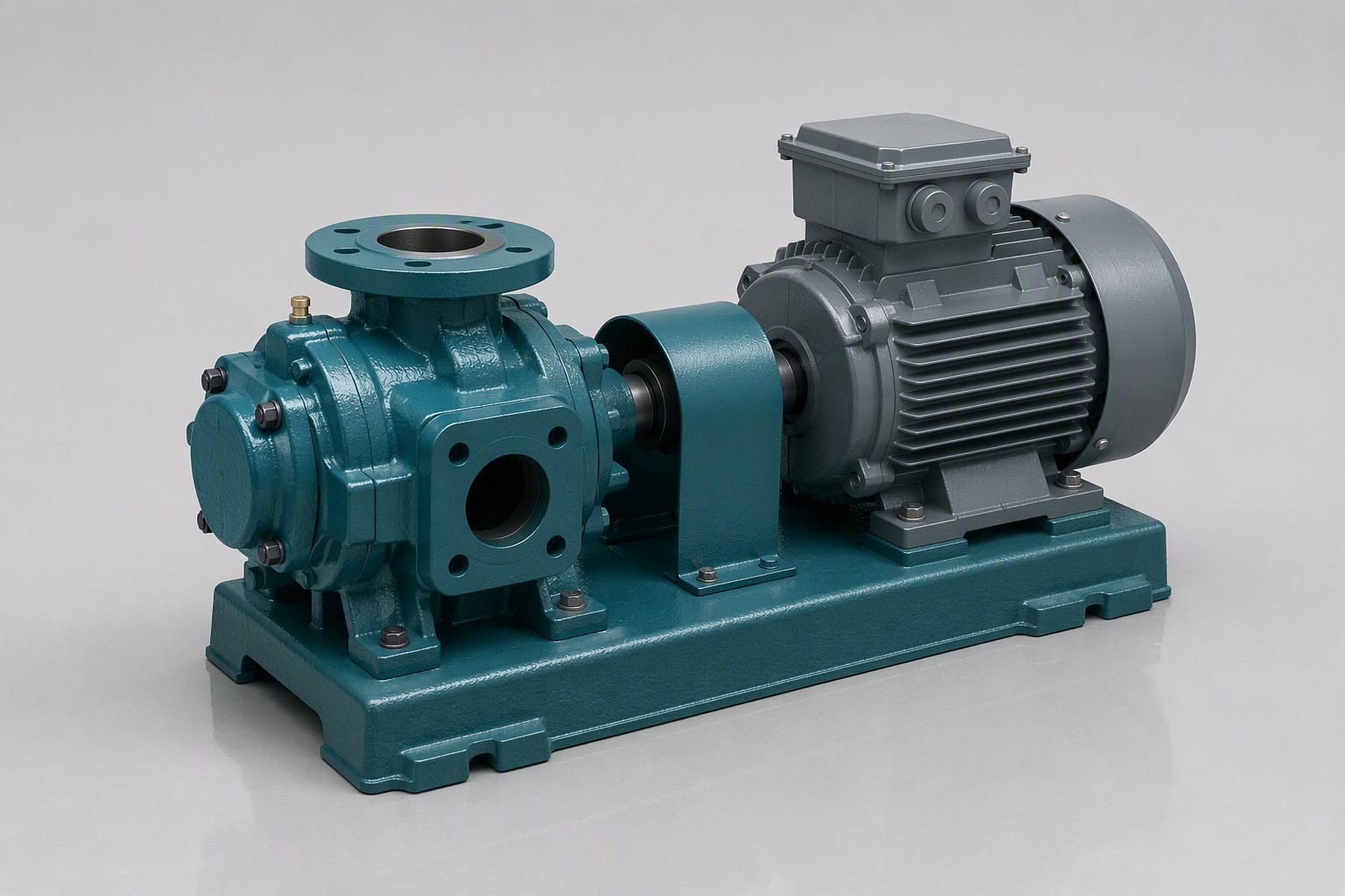
Define the Duty Before You Choose the Pump
The most common design error is picking a pump first and hoping the piping will suit it. Sound pump system design starts with two numbers: the duty flow and the total head the pump must generate at that flow. Total head is the static lift — vertical rise plus pressure difference between the vessels — plus every friction and minor loss in the pipe. Design for the worst realistic case as well as the normal one, and decide whether parallel pumps will share the duty.
The System Curve and the Pump Curve Must Meet
Plotting total head against flow gives the system curve: static head stays nearly constant while friction losses rise steeply with flow, and the pump's falling head-flow curve crosses it at the operating point. The designer's task is to make that intersection sit at the required flow — shifting it, if needed, with a control valve, variable-speed drive or impeller trim.
Pipe Sizing and Friction Losses
Piping consumes most of a pump system's energy. Oversized pipe is expensive to install; undersized pipe raises velocity, friction and erosion. Size for a sensible velocity for the liquid and duty, then calculate the friction loss of the actual pipe length, fittings and valves:
- Suction piping: keep it short and direct, never smaller than the pump suction nozzle, with no high pockets where gas can collect.
- Discharge piping: count the losses of every elbow, tee and valve, not just the straight pipe.
- Margins: add a stated working margin for ageing, fouling and future throughput instead of hiding it in oversized guesses.
NPSH and Cavitation: The Suction-Side Margin
Cavitation is a suction-side failure: when suction pressure falls to the liquid's vapour pressure, vapour bubbles form and collapse inside the impeller, eroding metal and cutting head and flow. So the system's available NPSH (NPSHa) must exceed the pump's required NPSH (NPSHr) at the operating flow, normally by roughly 0.5–1.5 m. Keep the suction lift low and the line short and large — every metre of suction friction loss is a metre of NPSH given away.
Viscosity, Temperature and Fluid Properties
Liquid properties change the whole design. Viscosity raises pipe friction and cuts the head and efficiency a centrifugal pump can develop, so above roughly 150 cSt a gear or screw pump is the better choice. Temperature sets material and seal limits and raises vapour pressure — a hot liquid cavitates more easily — so check the design at running and cold-start conditions. Fluid-specific guidance sits in the heavy oil transfer pump and chemical process pump selection guides.
Match the Pump Technology to the Duty
With the system defined, the technology choice is straightforward. Centrifugal pumps suit clean, thin liquids needing continuous, non-pulsating flow; positive displacement pumps hold flow steady on viscous media regardless of pressure. The table maps these duties to Qingdao Green Power series with verified ranges:
Technology Fit for Common System Designs
| System duty | Typical liquid | Pump family | Qingdao Green Power series (verified range) |
|---|---|---|---|
| Water and low-viscosity transfer | Water, process liquids | Centrifugal | IS/ISW: 1.5–1600 m³/h, head 2–125 m |
| Viscous, slurry and shear-sensitive media | Oil, resins, sludge, pastes | Screw (positive displacement) | G-type: 0.1–150 m³/h, 0.6–2.4 MPa |
| Vacuum and gas suction | Wet gases and vapours | Liquid ring | 2BV: 0.45–8.33 m³/min |
See the screw pump, centrifugal pump and vacuum pump product pages for construction details.
Special Duties Follow the Same Method
Exotic liquids do not change the method — they change the inputs. Boiler feed water needs high head against a hot, low-NPSH source — see the boiler feed pump selection guide. Hygienic food products add cleanability and gentle handling constraints — see the food grade pump selection guide. Liquefied gases such as LPG need vapour-pressure control and low-NPSH arrangements — see the LPG transfer pump article — and vacuum service follows the 2BV liquid ring vacuum pump selection guide.
Frequently Asked Questions
What is the first step in pump system design?
Define the duty before choosing a pump: the required flow rate and the total head made up of static lift plus piping friction losses. With those numbers you draw the system curve and select a pump whose curve crosses it at the required operating point.
What is NPSH and why does it matter in pump system design?
NPSH is the suction energy available at the pump inlet. Available NPSH (NPSHa) must exceed the pump's required NPSH (NPSHr) at the operating flow, normally by roughly 0.5–1.5 m, or the liquid cavitates and erodes the impeller. Keep the suction line short, direct and generously sized.
How does viscosity change a pump system design?
Viscosity raises piping friction and reduces the head and efficiency a centrifugal pump can generate, so above roughly 150 cSt a gear or screw pump normally becomes the better choice. Check the design at the cold-start viscosity as well as at running temperature, when line losses are highest.
Which Qingdao Green Power series fit typical pump system designs?
For water and low-viscosity liquids the IS/ISW centrifugal series is published at 1.5–1600 m³/h with 2–125 m head; for viscous, slurry or shear-sensitive media the G-type single-screw pump is published at 0.1–150 m³/h and 0.6–2.4 MPa; for vacuum service the 2BV series covers 0.45–8.33 m³/min. Confirm current model availability and specifications with Qingdao Green Power before procurement.
Send your duty point — flow, total head, liquid, temperature and suction layout — and the engineering team will review the system design and recommend the right pump configuration.
Get a Quote
Send your fluid data and duty point. Engineers reply within 24 hours.
Contact Us →💬 WhatsApp NowRelated Products
- IS/ISW Centrifugal Pump
- G & 3GB Screw Pump
- 2BV Liquid Ring Vacuum Pump
Related Articles
Boiler Feed Pump Selection Guide
High-head hot-water duty
Heavy Oil Transfer Pump
Viscous liquid transfer
Chemical Process Pump Selection
Corrosion and sealing